Sometimes the world of informatics overlaps strongly with the universe of human comprehension, and reaction component alignment is one of these cases: when reactants and products are drawn with a common orientation, it can be made very easy and immediately apparent to anyone with basic chemistry experience what is going on in the reaction. An arbitrary molecule layout on the other hand can impose a fairly high cognitive burden.
This is a series of articles about reaction prediction. The summary overview and table of contents can be found here. The website that provides this functionality is currently in a closed beta, but if you are interested in trying it out, just send an email to alex.clark@hey.com and introduce yourself.
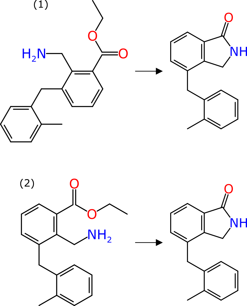
The graphic shown above renders the same reaction two different ways: in each case the product is identical in shape and form. In case (1) the reactant has its coordinates chosen well, but completely arbitrarily; in case (2) the reactant is drawn explicitly as the precursor to the product, with the reacting functional groups placed close by and as similar as possible to where they are in the product, and the whole thing is aligned to show commonality.
The difference between the two is quite stark: for case (2) an experienced organic chemist would observe the transform in a time measured in milliseconds. The cognitive load would be low enough that whole pages of such reactions could visually be scanned in an acceptable timeframe. For case (1), even an experienced chemist would see this and wonder what is happening: it requires the structure to be rotated and flipped and twisted as a mental exercise, in order to understand the transform. It would likely take a few seconds of proper concentration. And this is a really easy reaction.
It is surprising how few reaction informatics tools give any air time to this. Almost all chemical transforms that aren’t drawn out on a canvas by the chemist who performed the reaction just show the input & output molecules depicted freestyle. Sometimes they line up in a helpful way, sometimes they don’t.
Given that a reference molecule has been established, the technical solution to drawing the remaining components involves two parts:
- performing the molecule depiction layout with additional constraints
- orienting the new component in the same direction as the reference
Consider a reaction for which there is some atom-to-atom mapping available, but all atom coordinates are either missing or fair game for layout. The plan is:
- layout the coordinates for the product structure, in the usual way
- for each reactant:
- if there are at least 3 atoms mapped to the product, depict with special constraints
- (otherwise, depict normally)
- if there are at least 2 atoms mapped to the product, orient it to match the direction
- apply same logic to any byproducts, relative to reactants
The tools described in these articles use a depiction layout algorithm that is quite flexible by design, and allows the chunks of atoms to be biased in the ways that they are glued together. The important point here is that when you need to draw, say, a reactant so that it matches the product, the layout choices are not necessarily the optimal ones. Normally a depiction layout algorithm will try to find an embedding that follows preferred chemical drawing conventions (a lot of 120° angles) and maximises space between non-bonded atoms. But sometimes you want two atoms to be closer together, because once the reaction is done, they will be bonded.
This is done by enumerating all clusters of bonded atoms in the reference structure (e.g. the product) and mapped to atoms in the structure being depicted (e.g. the reactant). The bond distances, angles and torsions that are applicable get encoded as constraints. The scoring function for the depiction layout is heavily biased to try to match these, but not so heavily that it will do something crazy, like putting two atoms on top of each other.
Once the biased depiction is complete, the newly arranged molecule needs to be oriented. If there are two atoms in common with the reference structure, this will get the direction right most of the time. If there are 3 or more, a superimposition transform may involve a mirror image, which means that are needs to be taken to ensure that it does not accidentally invert the stereochemistry.
For visual presentation, it works even better if the transform itself is indicated:
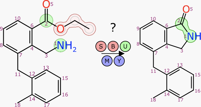
This operation follows the theme of these articles, that being generation of a complete reaction scheme: all structures present, all atoms accounted for and all roles implied. Aligned depiction works well at various stages of reaction composition, including when the atom mapping is only partial.
One way this machinery can show itself off is when pasting a reaction SMILES string into the web interface. If open gocatalysis.com now, and copy this onto the clipboard:
[CH3:2][CH2:3][O:4][C:5](=[O:6])[c:7]1[n:8][n:9][c:10]([Cl:1])[cH:11][c:12]1[NH2:13].[CH3:14][O:15][c:16]1[c:17](Br)[cH:18][cH:19][cH:20][c:21]1-[c:22]1[n:23][cH:24][n:25]([CH3:26])[n:27]1>>[CH3:2][CH2:3][O:4][C:5](=[O:6])[c:7]1[n:8][n:9][c:10]([Cl:1])[cH:11][c:12]1[NH:13][c:17]1[cH:18][cH:19][cH:20][c:21](-[c:22]2[n:23][cH:24][n:25]([CH3:26])[n:27]2)[c:16]1[O:15][CH3:14]
… what you will see is this:
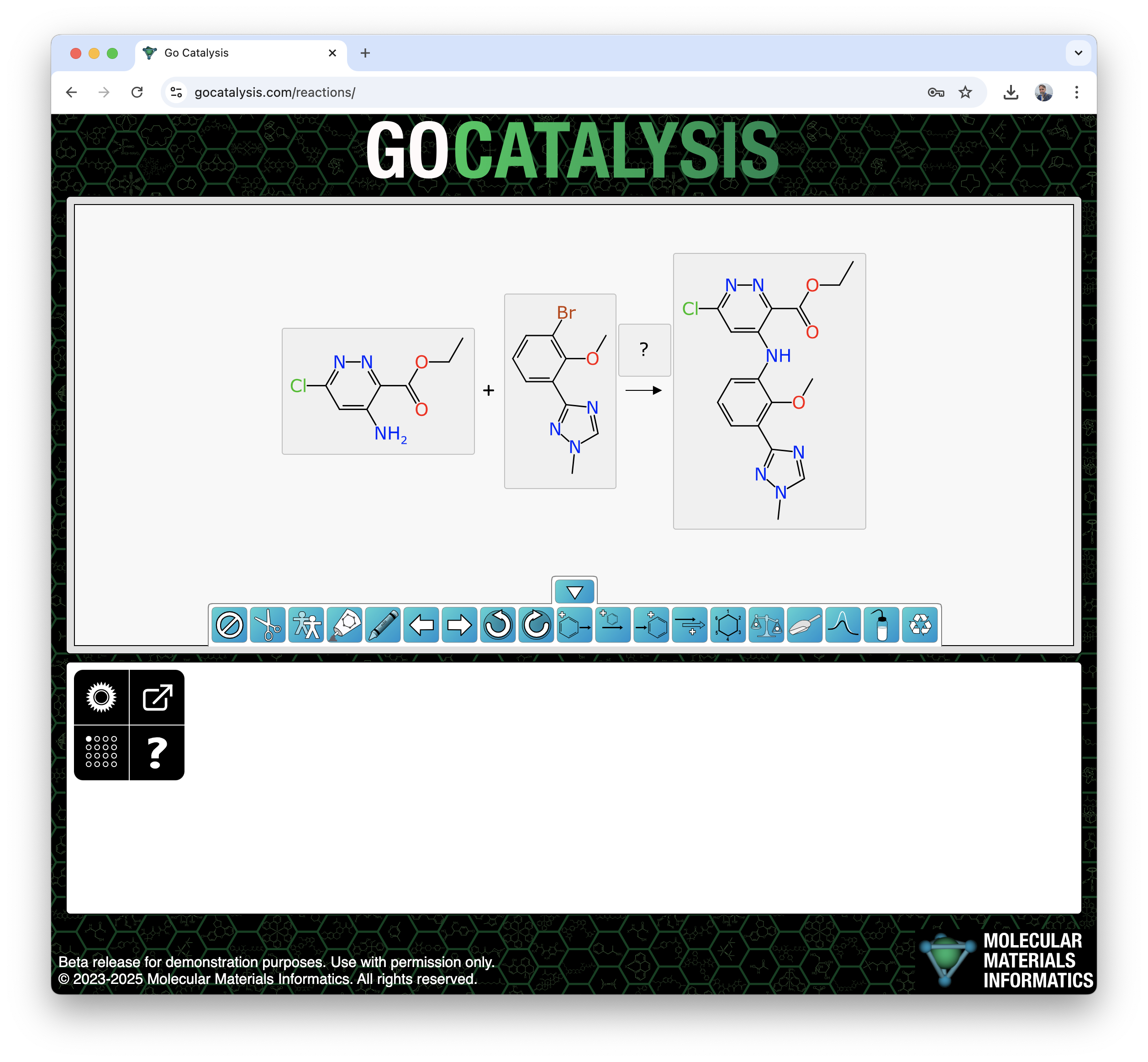
Having everything oriented and lined up is, needless to say, not a coincidence.
The next article is about reaction component-based editing.
